- Home
- >
- Perforated metal
What is Perforated Metal
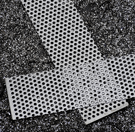
The applications of punched metals are wide, such as filter mesh and monument requiring high design quality.
Although a perforated metal is generally regarded as a kind of metal mesh, punching of any locations on metal is possible and bending and after-processing (e.g. hole processing) are easy. Compared with lath and crimp wire netting, perforated metals are processable without concavity or convexity.
Burring for making protrusive holes is also possible. As a dedicated perforated metal manufacturer, Uchinuki provides technical advices and consistent services such as mold manufacturing, punching-related secondary and tertiary processing and panel product manufacture. Uchinuki is actively developing new techniques such as Uchinuki graphic punching (UGP) system, knit/net-type punching series and the processing of materials in addition to metals.
Applications and materials
| Building exterior | Exterior panels in general, blind panel, balcony handrail, staircase blindfold, monument, soundproof walls for road, and signboards |
|---|---|
| Building interior | Ceiling panel, wall panel, partition screen and interior panel |
| Automobile | Speaker cover and muffler |
| Home electrical appliances | Speaker cover, heat dissipation cover, lighting cover, range hood filter, and for other filters. |
| Processing material | Punching of the following is possible: steel, aluminum, stainless steel, copper, titan, aluminum composite plate, other metals, PVC sheet, and other types of panels. Please consult us. |
|---|
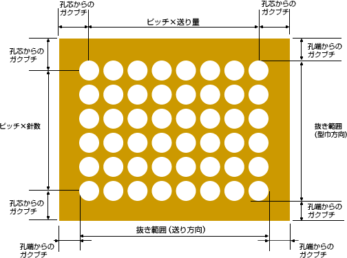
Hole arrangement and punching methods

Punching patterns and feeding directions
・Metal mold and hole arrangement for 60° houndstooth punchingMold arrangement in the case of houndstooth punching is shown in the right figure.
In this case, the shape of the first-perforated holes and that of last-perforated holes at both ends are different (holes are made asymmetrically) as shown in Figure 1.
Therefore, in the case of houndstooth pattern with different end shapes as shown in Figure 2, a one-line backfill is necessary.
[Figure 1] Asymmetrical houndstooth punching
![[Figure 1] Asymmetrical houndstooth punching](../img/about/anime_1B.gif)
[Figure 2] Symmetrical houndstooth punching
![[Figure 2] Symmetrical houndstooth punching](../img/about/anime_2.gif)
Houndstooth (staggered) punching and reverse houndstooth (staggered) punching
As shown in Figure 3, holes in the direction of shorter sides of the plate show a zigzag pattern, and the longer sides are feed direction.
Figure 4 shows a punching method different from that in Figure 3.
[Figure 3] Normal houndstooth (staggered) punching
![[Figure 3] Normal houndstooth (staggered) punching](../img/about/anime_3.gif)
[Figure 4] Reverse staggered (staggered) punching
![[Drawing 4] Reverse staggered (staggered) punching](../img/about/anime_4.gif)
Series punching (parallel punching)
In the case of series punching, if the hole interval has no problem, a one-line mold is used as shown in Figure 5.
[Figure 5]
![[Figure 5]](../img/about/anime_5.gif)
Skipping type
When the pitch is extremely narrow because of the relation between plate thickness and holes, processing may be difficult. In such a case, we use a skipping-type mold as shown in the figure before punching. Even after skipping-type punching, it is possible to manually fill holes to create a non-skipping pattern.
[Figure 6] Skipping pattern
![[Figure 6] Skipping pattern](../img/about/anime_10.gif)
[Figure 7] Non-skipping pattern
![[Figure 7] Non-skipping pattern](../img/about/anime_11.gif)
Margin
After punching, it is possible to maintain margins at the edges of the material.
There is a case where four margins remain at the four sides of the material and a case where margins remain partially such as in width direction.
Regarding margin size, please designate the distance from hole edge to material edge or from hole center to material edge.
It may be necessary to modify size requested by customer because of limitation in terms of mold size or punching pattern.
Automatic calculation of hole area rate
